CeraPiper
- My role
- Research intern, Cornell Tech x Technion, summer 2026; second author, ACM SCF 2026.
- Year
- 2026
- Type
- CAD tool, research
- Status
- Published, SCF 2026
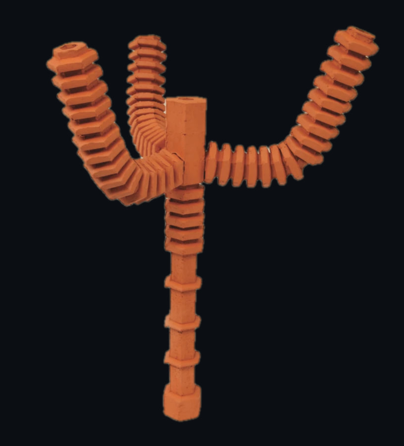
A chandelier-style cooling element, extruded on CeraPiper and assembled by hand. Filled with water, it cools the space around it as it evaporates.
- Published research paper at ACM SCF 2026, with a live demo; I’m second author, presenting in Tokyo.
- The tool holds the machine’s limits: 40–78 mm diameters, 30° rotation steps, a 150 mm span advisory.
- A printed paper blueprint runs under the clay, marking where to cut and where to hand-cut connector holes.
I was a research intern on CeraPiper, a CAD tool for designing custom hollow ceramic pipes that assemble into structures which cool a space by evaporating water. I’m second author of its CAD paper, a research paper published at ACM SCF 2026, which we present in Tokyo with a live demo.
Results
- outer diameter the die can produce
- 40–78mm
- maximum unsupported span before the sag advisory
- 150mm
- conveyor bed, minus 60 mm start and end pieces
- 800mm
(CeraPiper)
Versions
v1 to v2.0 predate my internship.
v1
17 July 2025
Submission to ACM SCF 2025.
v1.1
8 August 2025
Revamped extrusion data structure; unsupported-segment detection; 3D curve visualisation in beta; segment editing; a settings page; Arduino memory fixes.
v2.0
20 December 2025
Fixes and features from user-study feedback; full editing from the Function Stack; becomes an in-app Onshape extension.
v2.1
8 July 2026
Print order follows Onshape attachment order, so branches print as one contiguous chain.
about one Onshape API request per import · down from one request per part
v2.2
July 2026
Interactive paper blueprint; an Extrude action and per-bed tabs; branch pipes carve a matching hex hole in the host; ribbed branch profiles.
SCF 2026
6–8 December 2026
The CAD layer paper is published at ACM SCF 2026 and presented in Tokyo with a live demo.
Gallery
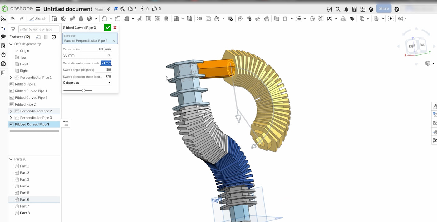
The design layer in Onshape
The design layer in Onshape: every pipe, curve and branch is a parametric feature, edited like any other CAD feature.
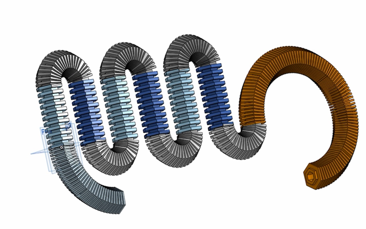
Composing an assembly
A whole assembly composed in Onshape; die sizes, bed length and sag limits are enforced as the geometry is shaped.
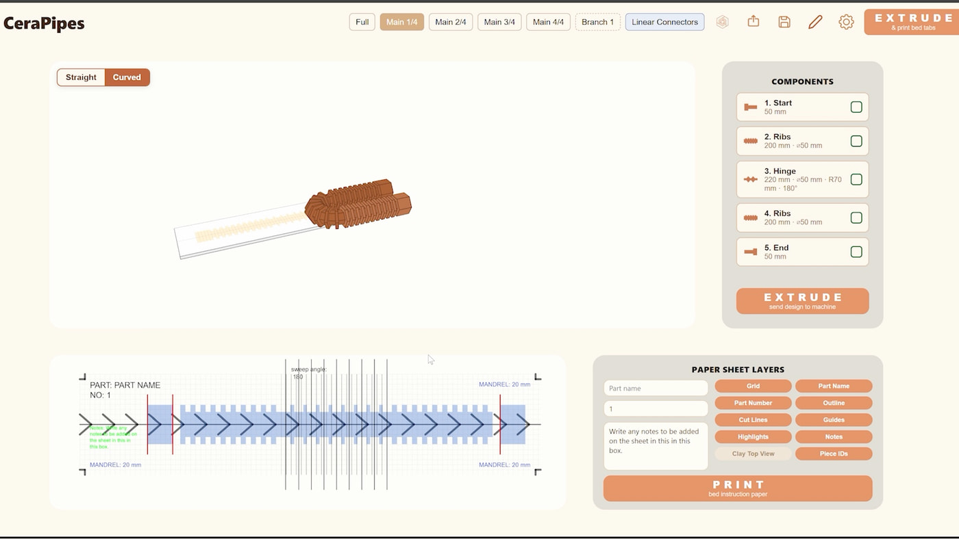
The CeraPipes app
The CeraPipes app: the design split into extrusion runs, sent to the machine, with the paper blueprint ready to print.
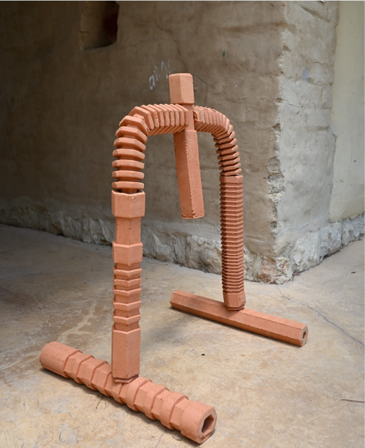
A cooling screen
An assembled cooling screen, designed in the tool and extruded on CeraPiper.
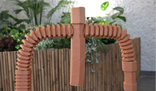
Assembled
Segments assembled into a ceramic structure for evaporative cooling.
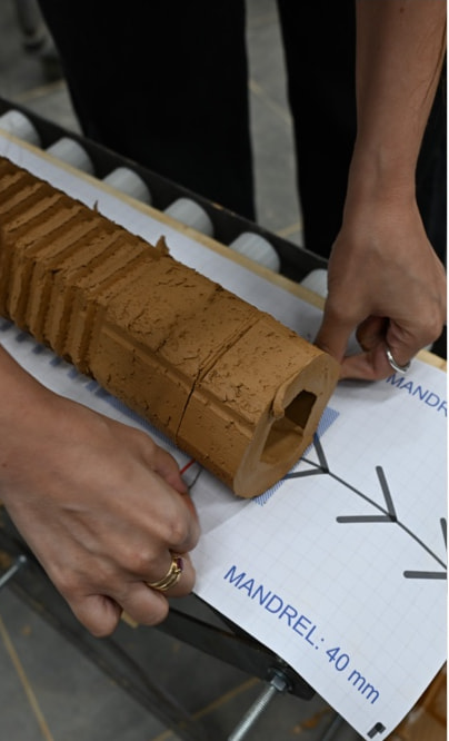
Extruded onto the blueprint
The printed blueprint runs under the clay as it is extruded.
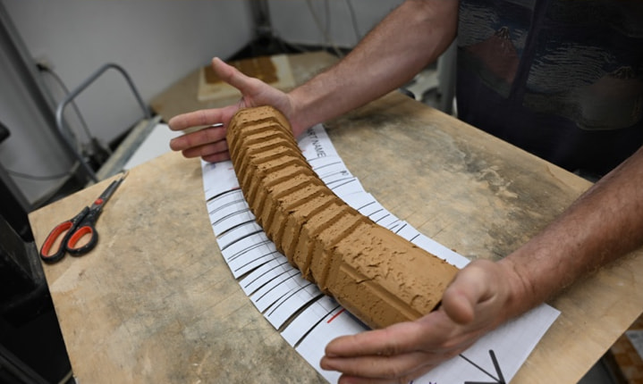
Finished by hand
Bending a pipe by hand along the blueprint’s cut lines.
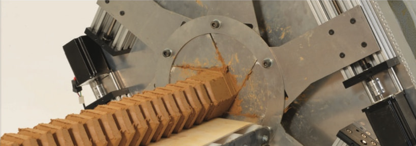
On the machine
A ribbed segment leaving the shape-shifting die on the pug mill.
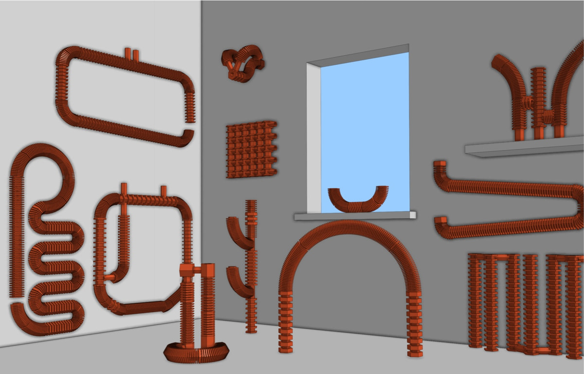
Twelve designers, one brief
Cooling screens designed by the twelve participants of our user study, from the same brief and the same primitives.
How it works
Every profile is hexagonal because the die is. The tool constrains what the machine can make: hard limits, corrections it applies for you, and advisories.
| Machine parameter | Design element |
|---|---|
| Die aperture travel | Outer diameter |
| Extrusion duration | Length in mm |
| Instruction order | Derived from how parts attach |
| Operator sag judgment | A 150 mm advisory |
Three software layers and one physical one: FeatureScript features in Onshape, Python and Flask middleware that compiles the feature tree into a JSON Function Stack, Arduino firmware at the machine, and the printed paper blueprint under the clay.
- 1
- Cut line, where the clay is divided into fabricable segments
- 2
- Fixed 60 mm start and end pieces at the limits of the 800 mm bed
- 3
- The mandrel size in use, drawn as the bore centreline
- 4
- Hex marker where a hole is hand-cut for a perpendicular connector
The paper blueprint: a 20 cm-wide sheet that runs along the bed under the freshly extruded clay, carrying the part name, where to cut, the mandrel in use and where to hand-cut a hole for a perpendicular connector.
Facts
- My role
- Research intern, Cornell Tech x Technion, summer 2026: CAD and slicing software for a custom ceramic printer. Second author of the CAD paper.
- When
- Summer 2026.
- With
- Matter of Tech Lab.
- Status
- The CAD layer is the subject of a research paper published at ACM SCF 2026 (Tokyo, 6–8 December 2026), with a live demo; I’m second author and present it in Tokyo. The earlier CAM version was published at ACM SCF 2025 (Berman, Seiz, Roumen; I am not an author).
- Stack
- Onshape FeatureScript; Python 3 and Flask; Arduino (C++); p5.js.
(Awards)
- Research paper published at ACM SCF 2026, with a live demoSecond author · Tokyo, 6–8 December 2026